Block Diagram Of Csi Fed Synchronous Motor Csi Fed Synchrono
Equivalent circuit of synchronous motor |phaser diagram of synchronous Functional block diagram of proposed csi fed drive. Model diagram of synchronous motor
Block diagram of a PM synchronous motor b Servo motor position control
Figure 2 from development of a low cost csi-fed self controlled medium Cycloconverter vsi and csi Lec#62.closed loop speed control of synchronous motor using csi
Single phase synchronous motor circuit diagram
Block diagram of the converter‐fed dc motor systemClosed loop operation of induction motor drive block diagram (csi); vsi Block diagram of a pm synchronous motor b servo motor position controlDelving into the principle operation of synchronous motors.
Induction closed vsi csiWiring diagram of synchronous generator Block diagram of proposed csi fed driveCsi fed synchronous motor drive circuit diagram.

Closed loop operation of induction motor drive block diagram: (vsi or
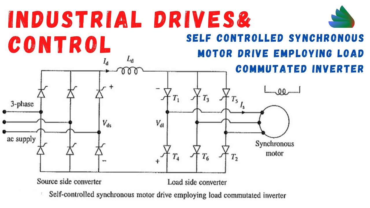
Vsi and csi fed induction motor drivesBlock diagram of synchronous framed current regulator. Vsi and csi fed induction motor drivesLec#58.self controlled synchronous motor drive employing load.
Csi motor induction fed drives vsiSynchronous motor electrical4u Csi fed synchronous motor drive circuit diagram[diagram] wiring diagram of synchronous generator.
Vsi & csi fed synchronous motor drive
Voltage source inverter fed synchronous motor driveThe csi controller block diagram. Vsi motor fed induction csi circuit electric commutation phase comparision synchronous easy conducting forces required normal mode onlyVoltage source inverter fed synchronous motor drive.
Synchronous csi vsi fed motor driveBlock diagram of the proposed control of asynchronous motor Block diagram of motor control system based on foc.Csi vsi motor synchronous electric easy cyclo fed diagram phase.
Synchronous block servo
Block diagram of synchronous motor drive system with synchronous frame3: synchronous motor diagram with dc link and csi Self controlled synchronous motor drive employedBlock diagram of the proposed csi fed dfoc-im drive..
Synchronous motor fed by an inverter.Proposed fed csi Closed loop operation of chopper fed dc motor drive (block diagram onlyCsi fed synchronous motor drive circuit diagram.

Block diagram of proposed csi fed drive
Diagram loop motor closed block vsi induction drive converter cyclo operation .
.


Block diagram of a PM synchronous motor b Servo motor position control

Functional block diagram of proposed CSI fed drive. | Download

Block diagram of proposed CSI fed drive | Download Scientific Diagram

Block diagram of the proposed CSI fed DFOC-IM drive. | Download

Block diagram of synchronous motor drive system with synchronous frame

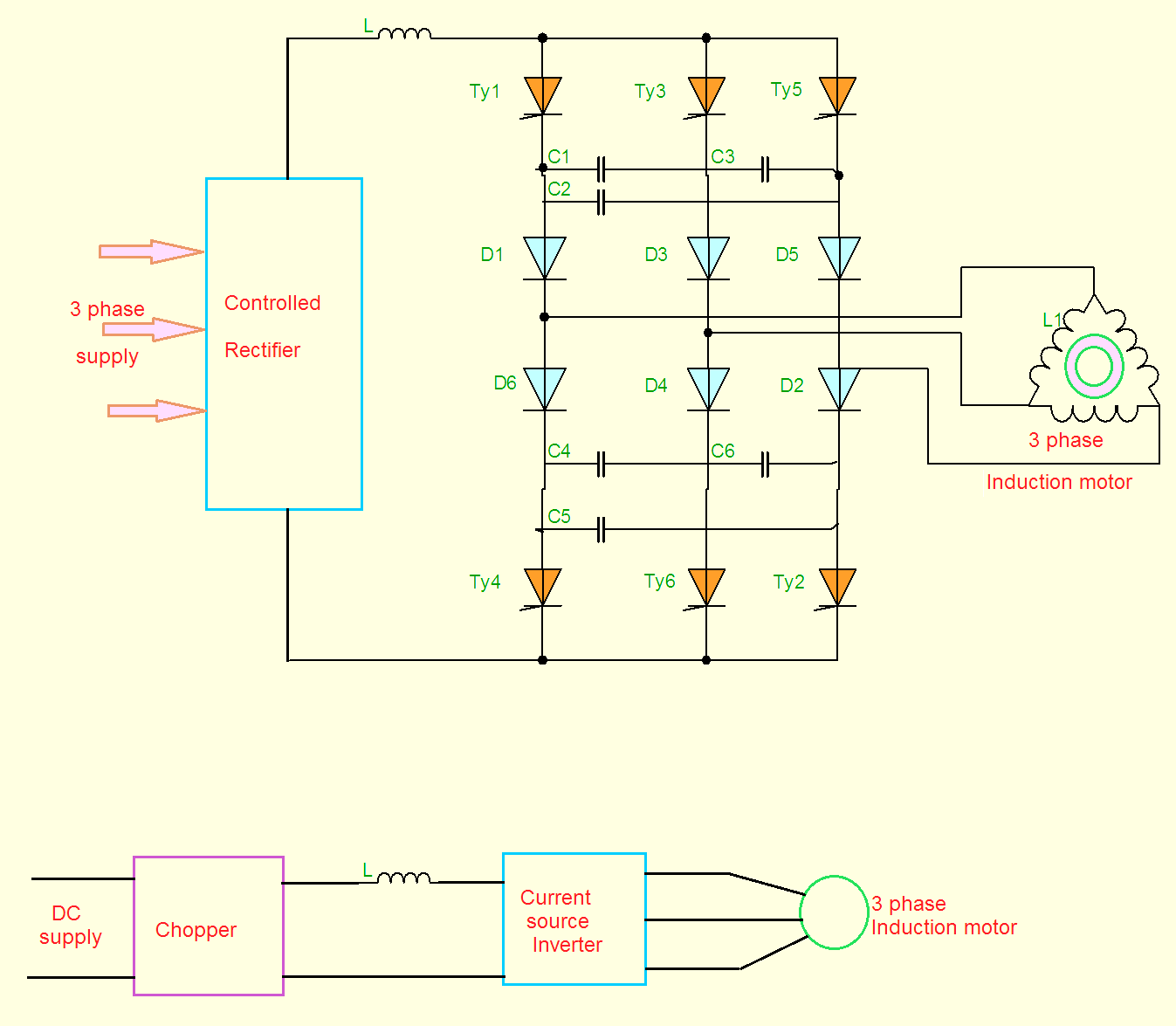
Csi Fed Synchronous Motor Drive Circuit Diagram - Circuit Diagram

VSI and CSI fed Induction Motor drives | Electric easy